Tensile test of welded specimen in Abaqus is a powerful method to evaluate how welding influences the mechanical performance and fracture behavior of a structure. In this detailed tutorial, we model a welded tensile sample, assign real material data for both base and weld metal, and simulate failure under dynamic explicit loading. The goal is to study how the presence of a weld changes stress distribution and crack propagation compared to an unwelded specimen. Ready? Let’s get started. tensile test of welded specimen in Abaqus
If you want to skip, download the files from here.
Table of Contents
Creating the Geometry and Weld Partition
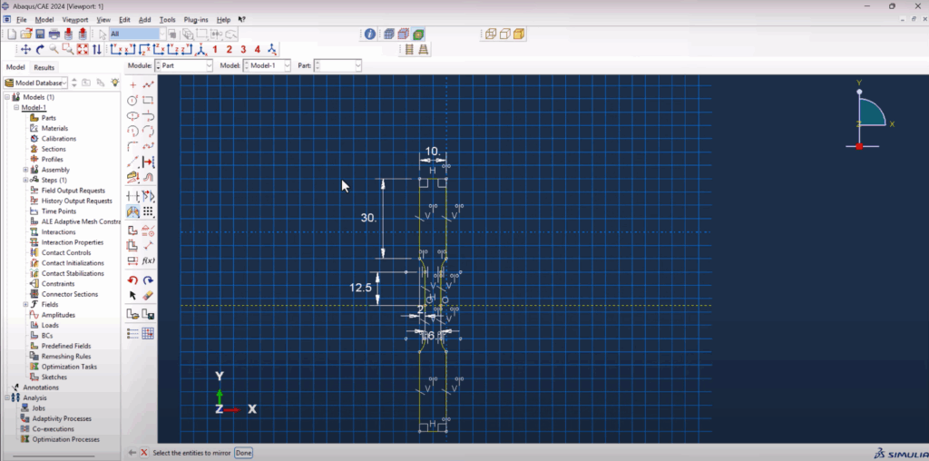
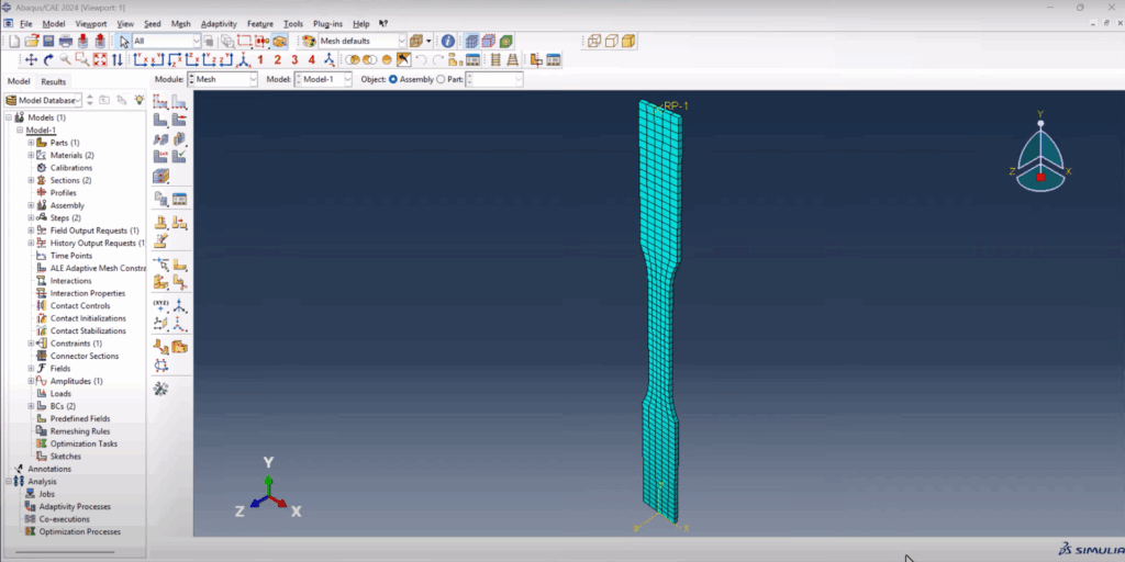
We begin by creating a 3D deformable solid part in Abaqus using the extrusion method. The model consists of two base metal regions and a central weld. To ensure symmetry and consistent dimensions, equal-length constraints are applied during sketching. The geometry is extruded to a depth of 1 mm to represent a thin plate.
Next, we partition the geometry to define the weld zone. Using a centerline and offset dimensions, we create a trapezoidal weld profile and mirror it to maintain symmetry. This weld region is then extruded through the model’s depth using the sweep along edge method. After that, each region (base and weld) is clearly separated, allowing for accurate material property assignment.
Material Properties and Section Assignment
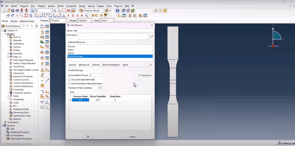
To simplify your workflow, you can download pre-made material property packs from FEA Master’s website. Once you have them, we define two materials in Abaqus: base metal and weld metal. tensile test of welded specimen in Abaqus
Base Metal includes density, elastic modulus, plastic behavior, and ductile damage properties.
Weld Metal is duplicated from the base metal, with only the plasticity and damage evolution values updated.
Sections are created for both materials and assigned to their respective regions using the Set by face option. To visually verify material assignment, we switch to the Material Display Mode, ensuring that base and weld zones are correctly colored and assigned.
Assembly and Step Definition
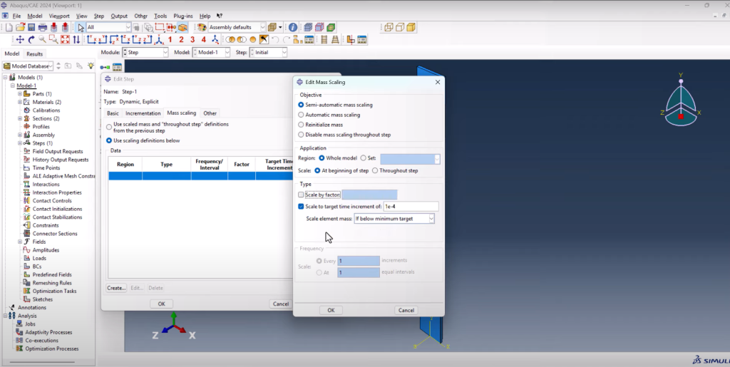
Since we’re using a single body model, the assembly step is straightforward. A Dynamic Explicit step is created, with mass scaling enabled to ensure a stable simulation. An important tweak here is turning on Status output in the field output manager. Without this, you won’t be able to visualize the crack or separation during failure. tensile test of welded specimen in Abaqus tensile test of welded specimen in Abaqus
tensile test of welded specimen in Abaqus
Loads, Boundary Conditions, and Amplitude
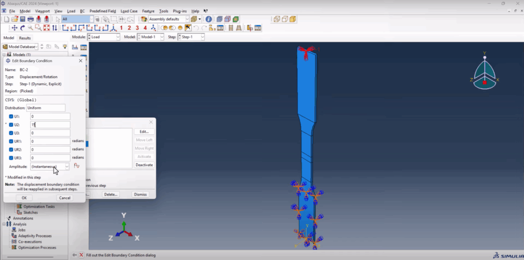
A reference point is created on one side of the specimen, and coupling is used to link it to a set of nodes. The opposite side is fixed using an Encastre boundary condition. The reference point is subjected to a displacement in the Y-direction (15 mm), which is applied gradually using a tabular amplitude (from 0 to 1). tensile test of welded specimen in Abaqus
Meshing the Model
The mesh is generated using global element size 1.0 mm. For educational purposes, the mesh is kept reasonably coarse, but the simulation still produces meaningful results. Using independent part instances allows us to apply a structured mesh even to the weld region.
Running the Job and Postprocessing
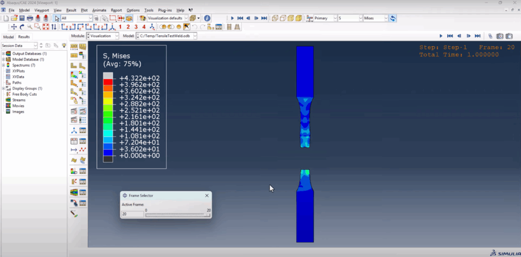
After defining the job and submitting it, we monitor for errors. The job completes successfully. Opening the result shows how the part deforms under tension. Notably, the weld does not fail—instead, the base metal experiences fracture first, which is a good sign that the weld parameters were appropriately defined.
tensile test of welded specimen in Abaqus
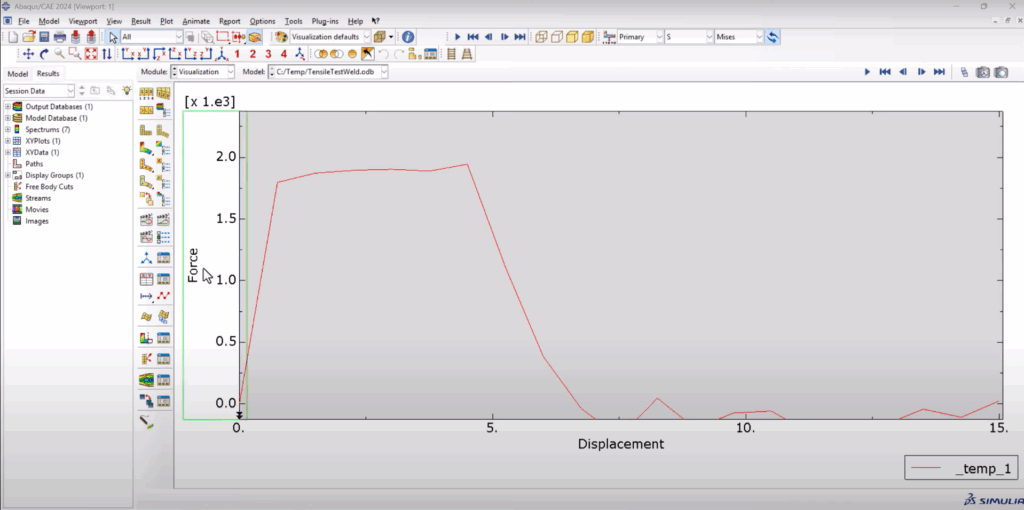
We then generate a force vs displacement plot by selecting the reaction force and displacement at the reference point. The result is a typical tensile curve that rises, plateaus, and then drops, indicating failure. This can be exported to Excel for further analysis or used to calculate stress-strain behavior manually, as explained in previous videos.
Conclusion
This tutorial walks you through a complete tensile test of welded specimen in Abaqus, showing how to simulate and analyze weld behavior under uniaxial loading. If you’re studying structural failure, welding effects, or material mechanics, this example will give you a clear roadmap for integrating weld zones into your simulations.
Don’t forget to watch the full video for a visual walkthrough, and download the ready-to-use Abaqus input files to save time.