Shear Failure Simulation in Abaqus
Shear Failure Simulation in Abaqus is the focus of this tutorial, where we walk through how to model, mesh, and simulate pin-connected structures under shear loads. Shear analysis of pin-connected structures is a critical task in structural mechanics, particularly in aerospace and mechanical applications where joints often become the weakest point. In this tutorial, we’ll walk through a complete simulation of shear failure in a pin structure using Abaqus. We’ll model the geometry, assign nonlinear material properties, apply realistic contact interactions, and run a dynamic explicit analysis to observe the damage and failure modes. This guide is designed for advanced users looking to simulate progressive failure behavior using ductile damage and accurate mesh controls.
Watch the full video from here:
Shear Failure Simulation in Abaqus: Step-by-Step Modeling Guide
Table of Contents
Creating the Geometry for Pin and Plate Structure
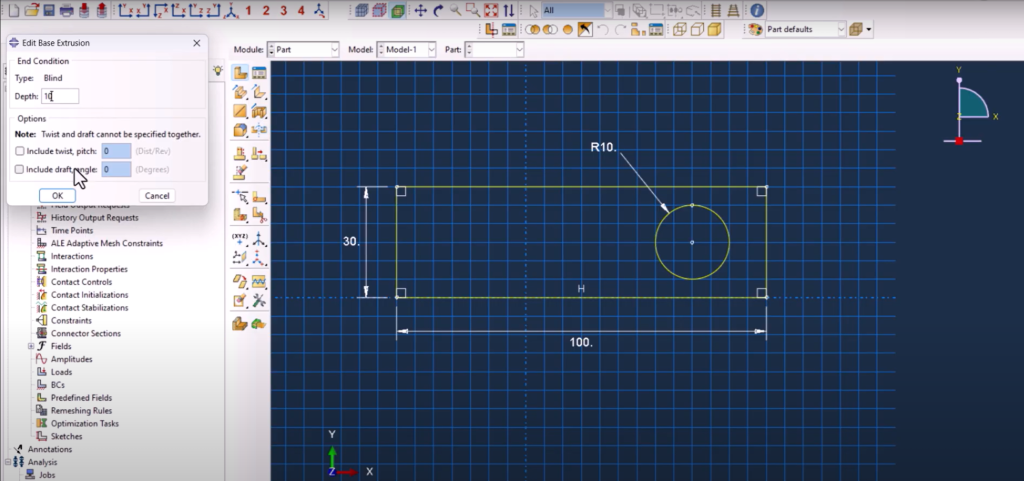
The first step is to create the main plate. We define a 3D deformable solid using the extrusion method and sketch a simple rectangular profile—30 mm wide and 100 mm long. A circular hole with a 10 mm radius is then added at the center to represent the pinhole. To ensure better meshing near the hole, we use partitioning tools to slice the geometry along strategic vertical lines. The pin is created separately as a 10 mm diameter and 20 mm tall cylinder, also modeled as a 3D deformable solid. Shear Failure Simulation in Abaqus
Assigning Material Properties with Damage and Plasticity
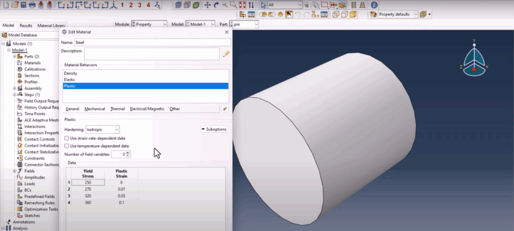
The plate and pin are both assigned a steel material model. The properties include density (7.8e-9), elastic modulus (210,000 MPa), and Poisson’s ratio (0.33). To simulate material degradation, we enable ductile damage using a plastic strain-based failure criterion. Under the mechanical menu, ductile damage is activated with user-defined damage evolution energy (0.4) and stabilization set to 1e-5. These properties allow Abaqus to handle the progressive failure under shear loads. Shear Failure Simulation in Abaqus
Assembly and Reference Point Setup
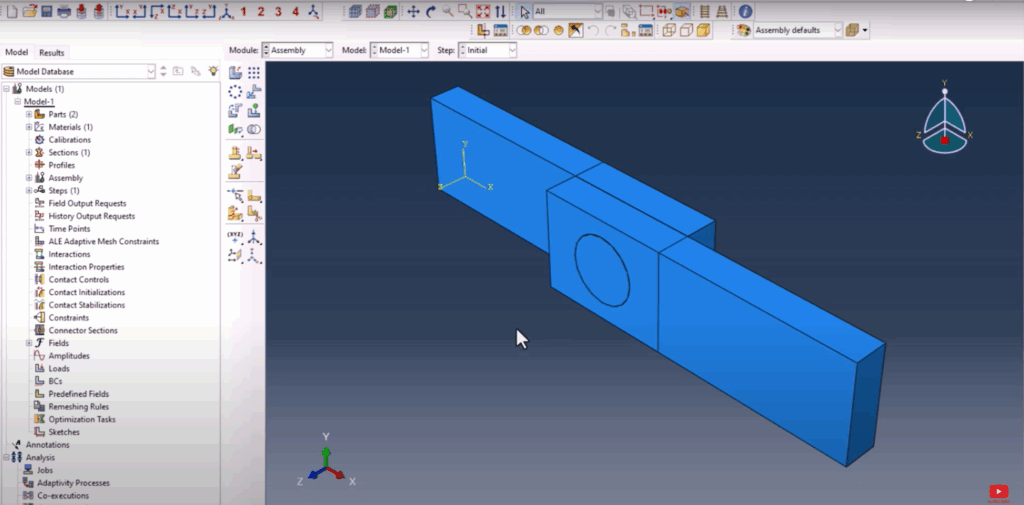
After defining the parts, the model is assembled. The two plates are positioned facing each other, with the pin placed in between. To apply the displacement laterally, a reference point is created above the pin and coupled with its body using a rigid body constraint. This step is crucial for applying accurate loads and observing displacement-driven failure behavior. Shear Failure Simulation in Abaqus
Step and Field Output Configuration
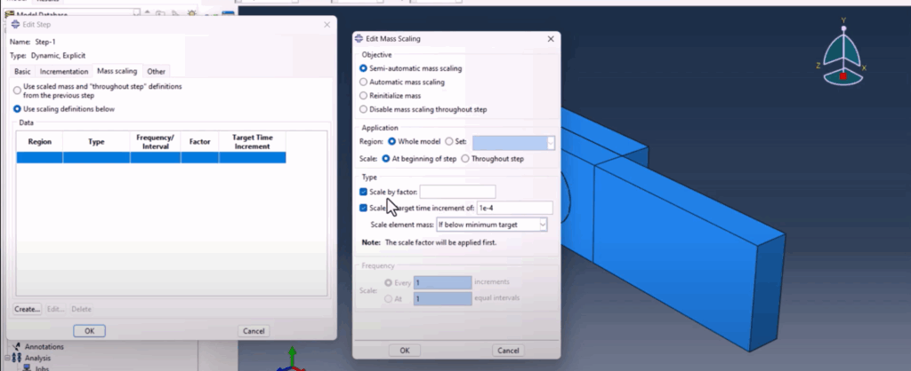
We set up a dynamic explicit step named Step-1 with total time 1.0 and NLGEOM enabled. An amplitude is created for load scaling—from 0 to 0.1 and then up to full amplitude—to simulate gradual loading. In the field output manager, we enable STATUS for element state tracking and damage indicators, which is necessary for visualizing the onset and growth of shear failure in postprocessing. Shear Failure Simulation in Abaqus
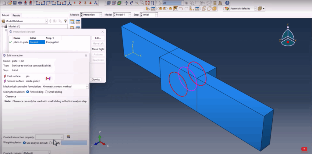
Defining Contact Interactions and Surfaces
Three main interactions are defined: plate-to-plate, plate-to-pin (left), and plate-to-pin (right). For plate-to-plate, we assign a frictionless contact. For plate-to-pin interactions, we introduce friction with a coefficient of 0.1 to simulate the pin’s resistance. All normal contact behaviors are set to “hard contact.” Using surface managers, we define specific contact areas manually to precisely control how surfaces interact. Shear Failure Simulation in Abaqus
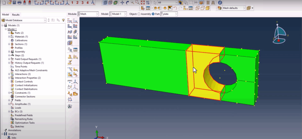
Partitioning for Structured Mesh
To ensure accurate results, structured meshing is applied to both the pin and plate. However, Abaqus doesn’t allow structured meshing around circular geometry without partitions. To resolve this, cutting planes are defined along strategic points on the circular boundary. This ensures the mesh lines up at all interfaces and avoids distortion. We seed the edges of the pin’s circumference with eight divisions and the plate thickness with three divisions, balancing accuracy and performance. Shear Failure Simulation in Abaqus
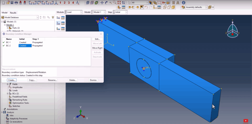
Applying Boundary Conditions and Loads
Two main boundary conditions are created. One encastre constraint fixes the bottom plate completely. Another displacement condition is applied to the reference point connected to the pin, moving it in the negative Y-direction by 5 mm. This load simulates the shearing force acting across the pin joint, mimicking real-world test conditions. Shear Failure Simulation in Abaqus
Submitting the Job and Reviewing Results
Once everything is in place, we create and submit the job. After completion, the results show the characteristic “shear-out” failure on the plate edges near the pin contact. We confirm that the damage is localized and occurs progressively, indicating that ductile failure was captured correctly. Visually, the damage resembles what’s commonly observed in experimental tests on shear pin joints. Shear Failure Simulation in Abaqus
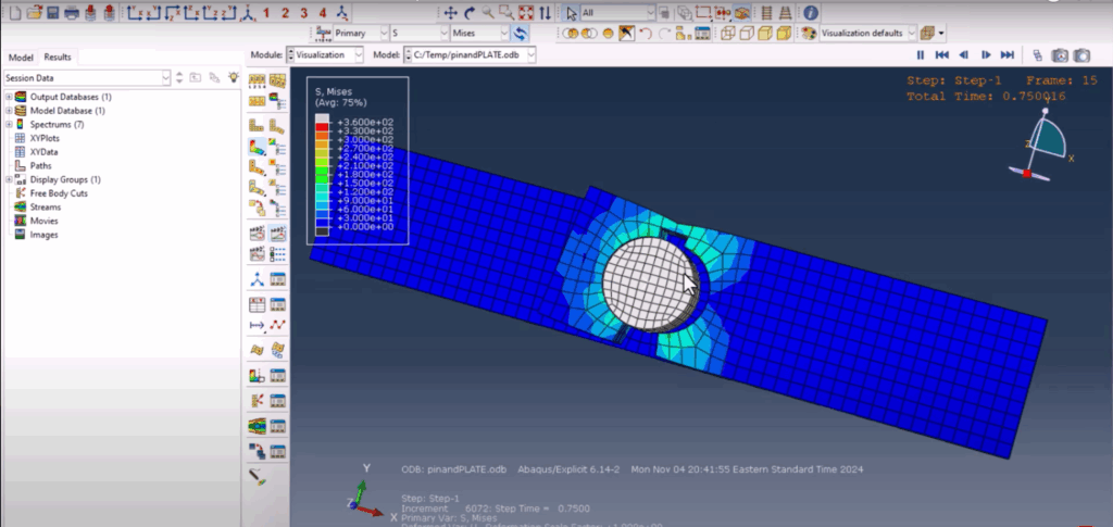
Shear Failure Simulation in Abaqus
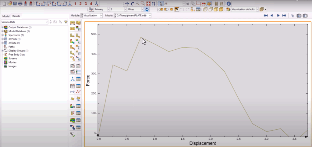
Force vs Displacement Plot and Validation
To understand the mechanical response, we plot force versus displacement using RF1 and U1 extracted from the reference point. The curve shows an initial linear response, followed by a peak load, and then a sharp drop due to the failure initiation—exactly what’s expected in shear failure of ductile materials. This behavior also matches literature trends from various published works, although we didn’t calibrate our model to a specific paper in this tutorial. Shear Failure Simulation in Abaqus
Conclusion
This simulation of shear failure in a pin joint structure demonstrates the power of Abaqus when paired with ductile damage and dynamic explicit steps. From meshing strategies to surface interactions and reference point loading, this walkthrough covers the essential techniques needed for realistic shear analysis. Whether you’re validating designs or studying failure mechanics, this approach gives you full control and deep insight into the structural behavior under shear loading. Shear Failure Simulation in Abaqus
You can watch the full video tutorial demonstrating the shear failure simulation in Abaqus step by step right here:
👉 Watch on YouTube
If you want to skip the setup and jump straight into postprocessing and analysis, you can download all the model files (CAE, INP, and result files) directly from the link below:
👉 Download the simulation files
If you found this tutorial helpful, don’t forget to subscribe to the channel and check out the next simulation walkthrough on the screen. Stay tuned!
