Lesson 1: SYSWELD Interface Introduction
Welcome to the first lesson of our SYSWELD course! In this lesson, we’ll dive into the SYSWELD interface, a crucial step in mastering welding simulations. SYSWELD’s interface is comprehensive, and understanding its layout and functionalities is key to effectively navigating and using the software for your projects.
Overview
In this lesson, we will explore the three main modules of SYSWELD: Visual Mesh, Visual Weld, and Visual Viewer. These modules form the backbone of your simulation process, each serving a distinct purpose in the workflow. Let’s break down what each module does and how they interact to provide a seamless simulation experience.
Watch the video introduction to get started:
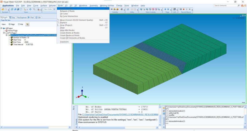
1. Visual Mesh
Visual Mesh is where your simulation begins. This module is dedicated to the creation and preparation of your model, acting as the foundation upon which all subsequent analyses are built.
Creating the Part: In Visual Mesh, you have the flexibility to create your parts using various tools. Whether you’re dealing with nodes, curves, or full 1D, 2D, or 3D models, this module provides all the necessary options to construct your simulation model accurately.
Mesh Generation: After creating your part, you can generate the mesh, which is essential for performing finite element analysis. Visual Mesh offers several options to refine your mesh, ensuring that your model is both precise and efficient.
Tools and Checks: Visual Mesh also includes tools for measuring, checking for coincident nodes or elements, and making necessary adjustments to your model. These features help in ensuring that your model is correctly set up before moving on to the simulation phase.

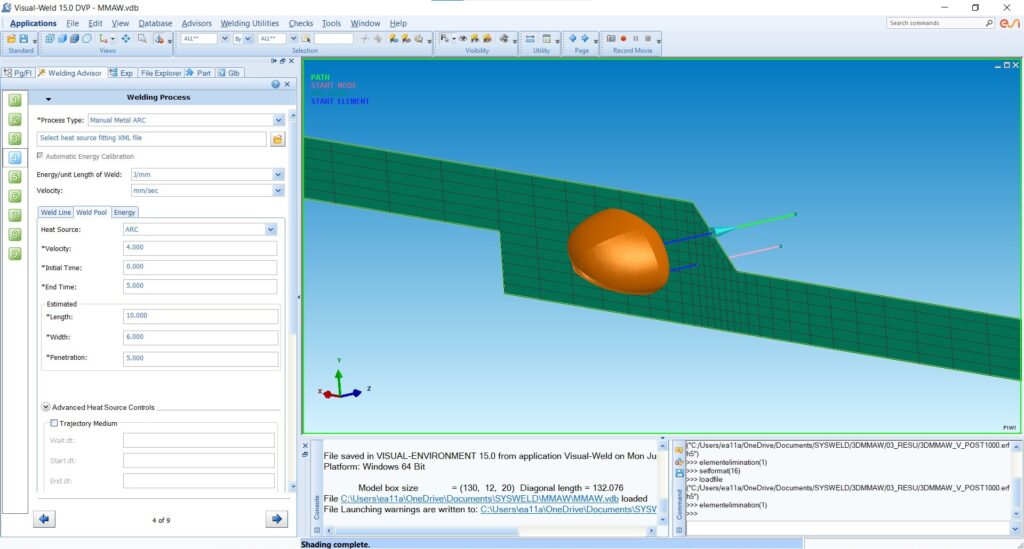
2. Visual Weld
Visual Weld is the core of SYSWELD, where the actual welding simulation takes place. After preparing your model in Visual Mesh, you transition to this module to set up and run the simulations.
Welding Parameters: In Visual Weld, you’ll define the key parameters that drive your simulation. These include material selection, heat source settings, welding speed, energy input, and more. The module provides advisors for different aspects like welding, heat treatment, and spot welding, guiding you through the setup process.
Heat Treatment and Clamping: You can also simulate post-weld heat treatments and apply clamping conditions to your model, making your simulations as realistic as possible.
Weld Bead Creation: Visual Weld allows you to create and simulate the weld bead, giving you insights into how different parameters affect the welding process and the final outcome.

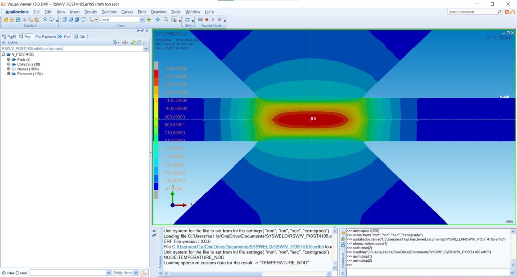
3. Visual Viewer
Finally, Visual Viewer is where you analyze the results of your simulations. After running your simulations in Visual Weld, you’ll switch to this module to review and interpret the outcomes.
Result Visualization: Visual Viewer displays the simulation results, such as temperature distributions, stress fields, and phase transformations during and after the welding process. You can see how the material reacts, with detailed visualizations of changes like phase transformations, including austenite and ferrite formations.
Phase Transformation: The viewer allows you to explore phase transformations in detail. For example, you can observe how the filler material is consumed during welding and how different phases emerge throughout the process.
Contour and Analysis: Use the Contour feature to visualize temperature fields, stress distribution, and other critical data. This helps in understanding the impact of your welding parameters on the final product.

Conclusion
This introduction to the SYSWELD interface sets the stage for the detailed simulations we’ll be conducting in subsequent lessons. You now have a basic understanding of the three main modules—Visual Mesh, Visual Weld, and Visual Viewer—each playing a vital role in the simulation process. As we move forward, you’ll become more familiar with each module’s functionalities, allowing you to conduct comprehensive and accurate welding simulations.
In the next lesson, we’ll start with a hands-on simulation, taking you through the process step by step using the Visual Mesh module. Stay tuned!
Proceed to Lesson 2: Setting Up Your First Welding Simulation